
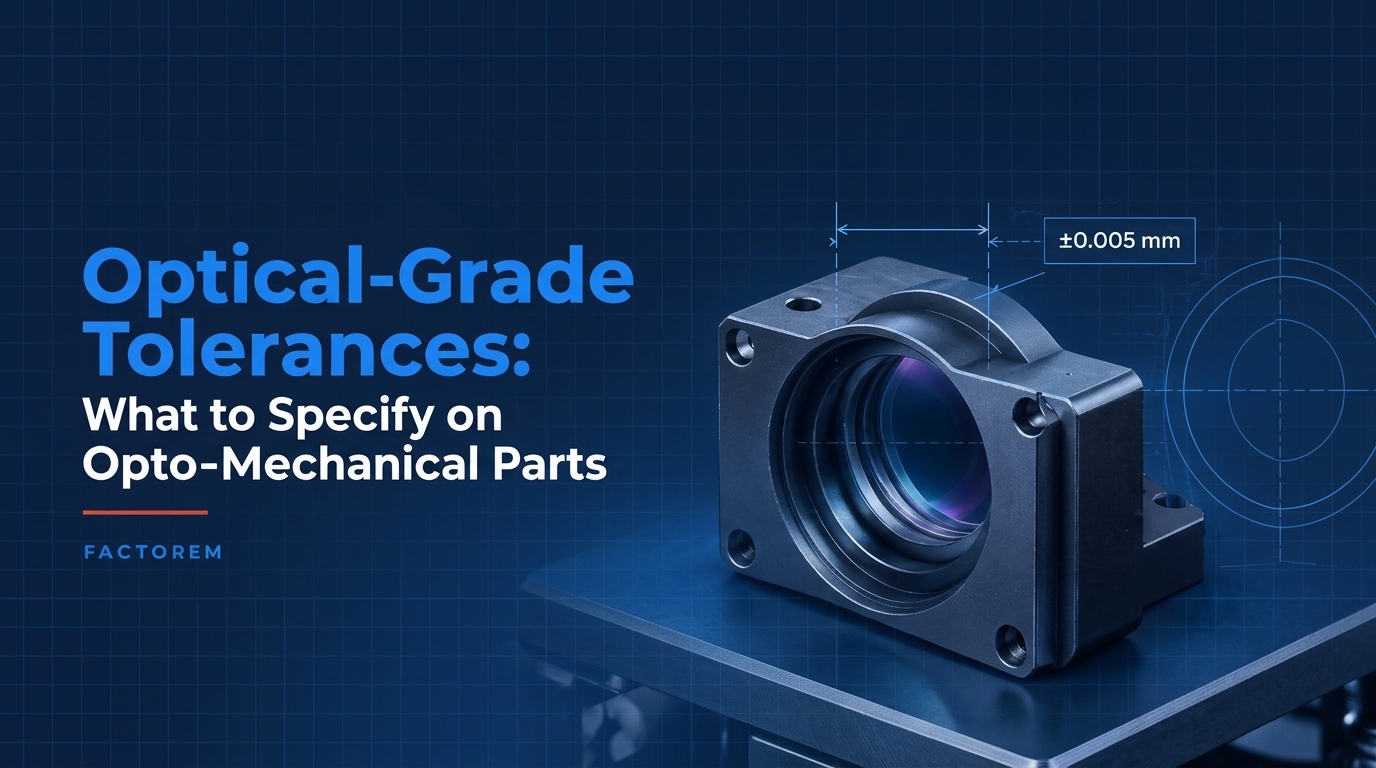
A lens seat can measure in tolerance on every dimension and still leave the optic decentred. The bore is within its limits, the shoulder is where the drawing says it should be, and the lens itself meets its catalogue specification. The problem is that nobody decided which of those dimensions controlled the thing that mattered, which was where the optical axis ended up.
This is the characteristic tolerancing failure in opto-mechanical parts. It rarely comes from a tolerance that was too loose. More often, tight tolerances were applied evenly across the part, and the few features that set the optical alignment were never distinguished from the many that do not.
Precision machining can hold very tight limits. The more useful skill is knowing where to ask for them.
Where optical tolerances actually matter
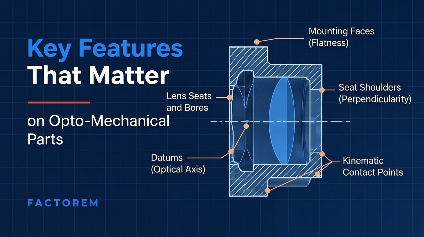
On most mounts, housings and lens tubes, the dimensions that control optical performance comedown to a short list.
Lens seats and bores. The bore diameter, together with the lens's own diameter tolerance, sets the radial clearance and therefore how far the lens can decentre.
Seat shoulders. The shoulder a lens registers against sets axial position (focus) and, through its perpendicularity to the bore axis, tilt.
Mounting faces. Flatness of the face that locates the part in the system decides whether the whole assembly sits true once it is bolted down.
Kinematic contact points. On kinematic mounts, the position and form of the contact features matter far more than the surrounding body.
Datums. A datum scheme built around the optical axis, rather than around whichever edge was convenient to draw from, is what makes the other callouts meaningful.
Everything else, including external profiles, clearance pockets, cable reliefs andcosmetic faces, can usually run at general tolerance without affecting the optics at all. Tightening those features adds machining time and inspection effort and does nothing for performance.
What is typically achievable
For CNC-machined opto-mechanical parts, typical working ranges are:
Critical features such as bores and flatness-critical faces: around ±0.005 mm.
General features: ±0.01 to 0.05 mm, depending on geometry and material.
Tighter limits on specific optical interfaces (around ±0.002 mm) are possible onrequest, and are reviewed feature by feature.
·Surface finish: Ra 0.8 to 3.2 µm as machined, with Ra 0.2 µm achievable by grinding on sealing and optical surfaces.
These are typical figures, not a guarantee for every geometry. A thin-walled tube, a long bore or a soft material will change what can be held, which is why tight limits are worth confirming with the manufacturer at the quotation stage rather than assumed.
Tolerance stack-up in a lens tube
Individual tolerances only tell part of the story. What the optic experiences is the sum of every tolerance between it and the reference that matters.
Consider a lensheld in a tube against a machined shoulder, separated from a second lens by a spacer, with a retaining ring behind it. If the shoulder location is held to ±0.01 mm, the spacer thickness to ±0.02 mm and the second shoulder to ±0.01 mm, the worst-case variation in the spacing between the two lenses is ±0.04 mm. A statistical (root-sum-square) estimate puts the likely variation nearer ±0.025mm. Whether either figure is acceptable depends on the optical design'ssensitivity to that spacing, which is a question for the optical engineer, not the machinist.
The practical point is that stack-ups belong on the drawing as a decision. If lens spacing is the critical output, the design can dimension both shoulders from a common datum instead of chaining them, which removes one contributor entirely. The spacer tolerance can then be tightened, or a spacer can be machined to measured size. Each of these is cheaper than tightening every dimension in the chain.
Radial clearance works the same way. The decentre budget is set by the bore tolerance and the lens diameter tolerance together, and the lens tolerance is often the larger of the two. It is worth checking the lens supplier's diameter specification before deciding how tightly the bore needs to be held.
Material and finish move the numbers
Two effects routinely change critical dimensions after the drawing has been finalised: temperature and coating.
Thermal expansion. Aluminium 6061 expands at roughly 23 µm per metre per °C. On a 25 mm bore, a 20 °C temperature change moves the diameter by about 0.012 mm, more than twice a ±0.005 mm tolerance. Stainless steel expands at roughly two-thirds that rate, and titanium at around a third. Where a mount must hold alignment across a temperature range, or must match the expansion of glass, material choice can matter more than the tolerance itself. Titanium is slower to machine, so lead times run longer, but they solve problems that no tolerance callout can.
Anodize build-up. Anodizing grows the aluminum surface as well as converting it, and roughly half the coating thickness builds outward. On a bore, that growth occurs on both sides, so the diameter shrinks by close to the full coating thickness. For a Type II anodize, this is a matter of microns. For hard anodize, it can be tens of microns enough to push a precision bore out of tolerance.
Depending on your design requirements, there are two standard ways to handle this:
Machine with an allowance: If the feature requires anodizing, the manufacturer will machine the part with sufficient material allowance beforehand to ensure the final dimensions are accurate after the coating process.
Mask critical features: if masking is preferred for critical bores and seats, include clear masking instructions directly on the part's 2D drawing.
Black anodize is common on optical parts because it suppresses stray light, and it is worth treating as part of the tolerance question rather than as a separate cosmetic choice.
How to call it out on the drawing
A drawing that makes the critical features obvious is the most reliable way to get them made correctly first time.
Build the datum scheme around the optical axis. Reference the lens bore or seat as the primary datum where the optics depend on it.
Use the right geometric controls. Perpendicularity for seat shoulders, flatness for mounting faces, and circular or total runout for coaxial bores. Current ASMEY14.5 practice favours run out or position over concentricity for coaxial features.
Put tight limits only on the features that carry the fit. Unmarked dimensions default to standard ISO general tolerances, so the useful signal is marking the few where that default is not enough.
State finish and its relationship to dimensions. Specify the finish type, clearly note which surfaces are to be masked on the 2D drawing, and explicitly state whether dimensions apply before or after anodization. To be safe, always call this out though in most cases, drawing dimensions are assumed to apply after anodization.
·Record anything deliberate. An offset seat, an unusual clearance or an intentionally loose fit is worth one line in a note. Intent is the one thing a manufacturer cannot infer from the geometry.
That last point matters more on optical parts than almost anywhere else. A seat drawn 0.05 mm off-centre on purpose looks exactly like a mistake, and a mistake looks exactly like a deliberate offset.
Before you upload
Five checks catch most of the issues that turn into clarification questions after an order has been placed:
1. Are the optical datums defined from the features the optics actually register against?
2. Are tight tolerances limited to seats, bores, shoulders, mounting faces and contact points?
3. Has the lens supplier's diameter tolerance been included in the decentre budget?
4. Is the operating temperature range compatible with the chosen material?
5. Does the drawing say which surfaces are masked and whether dimensions apply after finish?
Factorem's DFM Guide and Pre-Submission Checklist covers the wider set of checks for CNC, sheet metal and 3D-printed parts.
Getting opto-mechanical parts made
Factorem machines parts like lens mounts, kinematic mounts, filter holders, detector housings and alignment stages for photonics and optics teams, in materials from 6061 and 7075 aluminium to stainless steel, and titanium. Design checks run before manufacture, and engineers review complex and tight-tolerance parts, so questions about seats, finishes and stack-ups are raised at the quotation stage rather than after the purchase order.
See the photonics and optics parts we machine and the CNC machining specifications, upload a CAD file for a quote, or talk to an engineer about a part that needs tighter limits than thoselisted.


