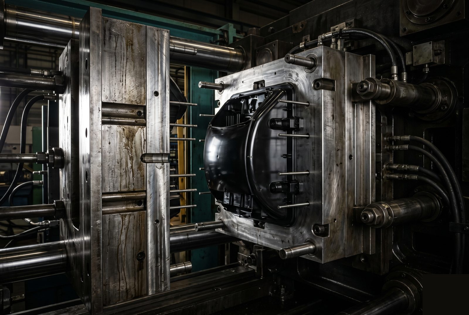
Injection Molding for Enclosures, Housings, and Structural Plastic Parts.
Factorem handles injection molding from tooling design through production — with engineer-led DFM review, first article inspection, and ISO 9001 quality controls on every order.
±0.1mm
Typical tolerance
2–4 wks
Prototype tooling
50–50k+
Production range
ISO 9001
Certified
Typical Capability Specs
Common parameters for injection molding at Factorem. Final specs depend on material, geometry, and tooling — our engineers confirm these during DFM.
Standard Tolerance
±0.1–0.2mm
Typical for most features. Critical tolerances to ±0.05mm with appropriate tooling and process control.
Wall Thickness Range
1.0–4.0mm
Optimal range for most engineering plastics. Uniform wall thickness reduces sink and warpage.
Prototype Tooling Lead Time
2–4 weeks
Aluminium prototype tooling. Production steel tooling 4–6 weeks depending on complexity.
Draft Angle
1–3° typical
Required on all vertical faces for part ejection. Textured surfaces typically need 3–5°.
Max Part Envelope
500×400×200mm
Typical for standard tooling. Larger parts reviewed on request — shot weight and clamp tonnage reviewed case by case.
Production Range
50–50,000+
Prototype quantities to production volumes. Tooling amortised across the run; unit cost decreases at volume.
Common Materials
Engineering plastics commonly used in injection molding at Factorem. Other grades, colours, and filled variants available on request.
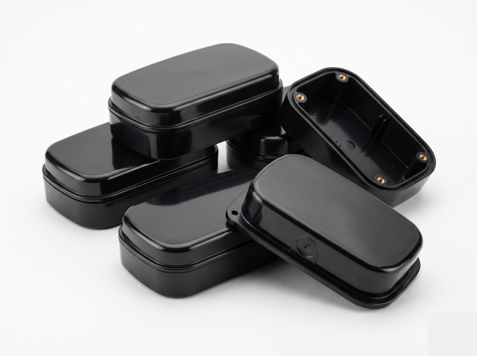
ABS
Workhorse engineering plastic. Good impact strength, easy to mold, accepts a wide range of surface finishes and paints. Standard for consumer electronics housings, equipment enclosures, and prototype parts.
Commonly used for
Equipment housings, covers, brackets, connectors
Polycarbonate (PC)
High impact strength, dimensionally stable, and optically clear in natural grade. UV-resistant grades available. PC/ABS blends offer improved impact plus easier processing than unfilled PC.
Commonly used for
Transparent covers, light guides, safety-critical housings, instrument panels
Nylon PA66 / PA6
High strength-to-weight ratio, good chemical resistance, and fatigue resistance. Glass-filled grades (PA66-GF30) offer higher stiffness and lower creep. Hygroscopic — moisture content affects dimensions and processing.
Commonly used for
Gears, pulleys, cable guides, structural brackets, wire management
PEEK
Exceptional thermal stability (continuous use to 250°C), chemical resistance, and mechanical strength. High processing temperature requires appropriate tooling and equipment. Costly — best reserved for applications where lower-cost materials can't meet the requirements.
Commonly used for
Medical devices, vacuum system components, high-temperature structural parts
Polypropylene (PP)
Lightweight, chemically resistant, and fatigue-resistant — excellent for living hinge features. Lower stiffness than ABS but cost-effective for high-volume applications. Good for parts with snap-fit features.
Commonly used for
Living hinges, containers, covers with snap-fits, fluid-contact parts
Other Materials & Overmolding
PPS, LCP, Acetal (POM), TPU/TPE for overmolding, glass- and carbon-filled variants — reviewed on request. Share your material requirement and application and our engineers will advise on suitability and processing.
Unsure which plastic is right for your application? Our engineers can help select the right material based on your mechanical, thermal, and environmental requirements. Talk to an engineer →
Don't see what you need?
Unusual material, complex undercuts, insert molding, or overmolding requirements? Our engineers review non-standard requests — most can be accommodated.
What We Can Make
Injection Molding Process Types
Common process variants Factorem supports. If your application needs something not listed here, talk to our engineers.
Custom Plastic Injection Molding
Thermoplastic resin injected into a custom steel or aluminium tool to produce consistent parts at volume. The core process — used for the majority of plastic enclosures, housings, and structural parts.
Commonly used when
Producing ABS, PC, Nylon, or PP parts in quantities from 50 to 50,000+
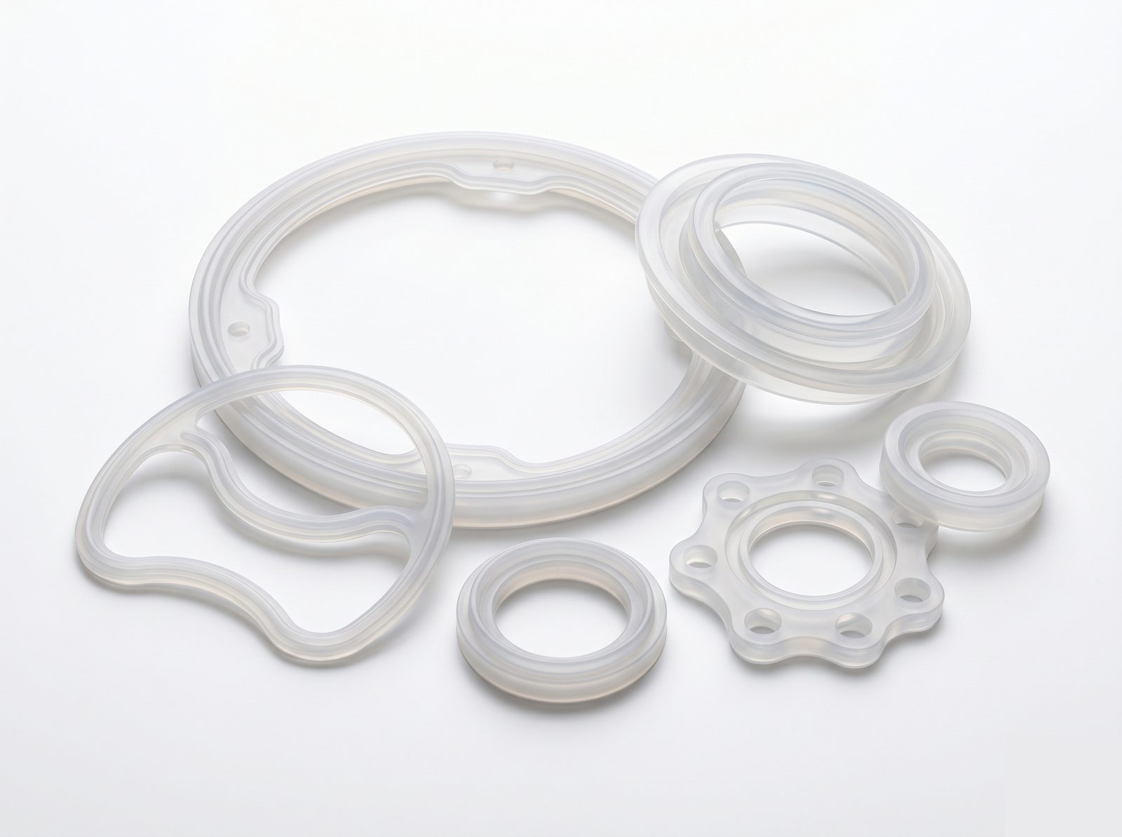
Liquid Silicone Rubber (LSR) Molding
Two-part platinum-cured silicone injected into a temperature-controlled mold. Produces flexible, biocompatible parts with excellent chemical and temperature resistance.
Commonly used when
Parts need flexibility, sealing function, or biocompatibility — seals, gaskets, wearable interfaces, medical components
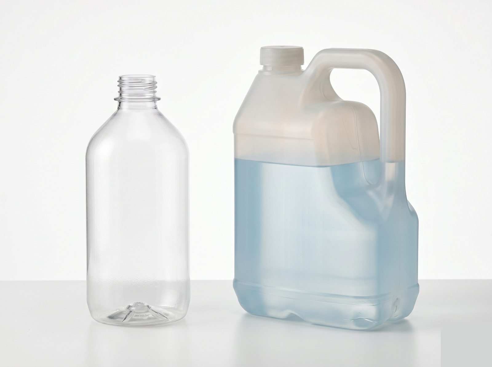
Blow Molding
A heated plastic parison is inflated inside a mold to create hollow parts. Suited to bottles, tanks, and enclosed duct shapes that cannot be produced with conventional injection tooling.
Commonly used when
Parts are hollow with a continuous wall — fluid containers, cable ducting, protective covers
2-Shot / Overmolding
Two materials — typically a rigid substrate and a soft overmold — are molded in sequence, either in one tool (2-shot) or two (overmolding). Produces integrated two-material parts without adhesives or assembly.
Commonly used when
Parts need soft-touch grips, sealed interfaces, or colour differentiation between materials
Need a process not listed here — insert molding, micro-molding, or a hybrid approach? Describe your application and our engineers will advise. Talk to an engineer →
Industries & Applications
Injection molding is used wherever consistent plastic parts are needed at volume. Commonly used across these industries — but not limited to them.
Photonics & Optics
Lens filter holders, fiber connector housings, light baffle components, protective covers for optical assemblies — often in black-dyed ABS or PC
See Photonics page →
Quantum
Wiring harness strain reliefs, rack cable management components, low-outgassing PEEK fittings for vacuum systems, equipment housings for control electronics
See Quantum page →
Robotics
End-effector body shells, cable drag chain links, sensor housings, protective covers for electronics on robot arms, ABS/PC enclosures for control modules
See Robotics page →
Defense & Aerospace
Connector backshells, grommet seals, cable management inserts, protective covers for EAR99 commercial programs — in glass-filled nylon or PC
See Defense page →
Space Tech
Low-outgassing PEEK connectors, ground support equipment plastic components, harness routing clips and brackets for satellite integration
See Space Tech page →
Other Applications
Medical device enclosures, semiconductor tooling inserts, industrial automation components — if you're producing a plastic part at volume, tell us about it.
Design Considerations
Before You Send Your File
Common design factors for injection molded parts. These are guidance — send your design and our engineers will review it regardless.
Draft Angles on All Vertical Faces
Faces parallel to the pull direction need 1–3° draft to release cleanly from the mold; textured surfaces typically need 3–5°. Zero-draft features are possible with side-pulls but add tooling cost.
Uniform Wall Thickness
Thick sections cool unevenly, causing sink marks or warpage — aim for 1.0–4.0mm uniform walls. Where thick sections are unavoidable, coring out reduces mass without losing stiffness.
Gate & Parting Line Placement
Gate marks are visible — place gates on non-cosmetic surfaces where possible. Confirm parting line location early; it determines where the visible seam sits and where flash can form.
Undercuts and Side Features
Undercuts prevent straight ejection and require side-pulls, lifters, or collapsible cores — adding tooling cost. Where possible, redesign undercuts to be form-through or accessible from the parting line.
Complex geometry — multiple undercuts, tight tolerances, or unusual materials?
Talk to our engineersHow an Injection Molding Order Works
Upload Your Part File
Send STEP with your drawing. Include material, colour, surface finish requirement, and any insert or overmolding specs. For assemblies, include the mating context.
DFM Review — Within 24 Hours
Our engineer reviews draft angles, wall thickness, gate placement, parting line, undercuts, and material suitability. Any issues are flagged with suggested fixes before tooling cost is committed.
Confirm Quote, Tooling Type & Material
Fixed-price quote covering tooling + production run. Confirm aluminium or steel tooling, resin grade, colour, and first article requirements.
Tool → First Shots → Approve → Production
Tooling is machined, first shots are produced and measured against your drawing. You review and approve before the production run begins. Process parameters are locked for consistent parts across the run.
Inspection, Documentation, & Delivery
Certificate of Conformance and dimensional inspection report on every order. Material certification from resin supplier. FAI report available. Tracked shipment with full handover pack.
Injection Molding FAQ
Typical dimensional tolerance is ±0.1–0.2mm for standard features, depending on material, wall thickness, and part geometry. Critical features can be held to ±0.05mm with appropriate tooling and process control. Our DFM review identifies which features in your design need special attention before tooling is cut.
There is no hard minimum — we work with prototype quantities (50–500 pieces) through to production runs (10,000+ pieces). Tooling is amortised across the run, so unit cost decreases significantly at higher volumes. Our engineers will help you decide whether injection molding or 3D printing is more economical for your quantity and timeline.
Aluminium prototype tooling typically takes 2–4 weeks. Production steel tooling takes 4–6 weeks depending on part complexity. First shots are reviewed with you before production begins. For parts that can tolerate slightly looser tolerances, aluminium tooling with shorter lead time is often the right choice for early production quantities.
Yes. We mold PEEK, PPS, LCP, and other high-performance materials that require higher melt temperatures and controlled tool temperatures. These materials need appropriate tooling steel and process controls. Contact us with your material and application — our engineers will confirm suitability and advise on design requirements.
Yes. Insert molding (metal inserts, threaded brass inserts, pins) and overmolding (soft-touch grip materials, two-material parts) are available. Insert location and orientation affect tooling design and should be specified early in the DFM process. Send your design and we'll advise on the best approach for your assembly.
Standard documentation includes a Certificate of Conformance, dimensional inspection report for critical features, and material certification from the resin supplier. First article inspection (FAI) report available. Full quality documentation pack available for programs with specific documentation requirements — contact us to discuss.
Ready to Mold Your Next Part?
Upload your STEP file for a DFM review and tooling + production quote — or talk to an engineer about your material and quantity requirements.
DFM review within 24 hours · Fixed-price quote · Full documentation on every order