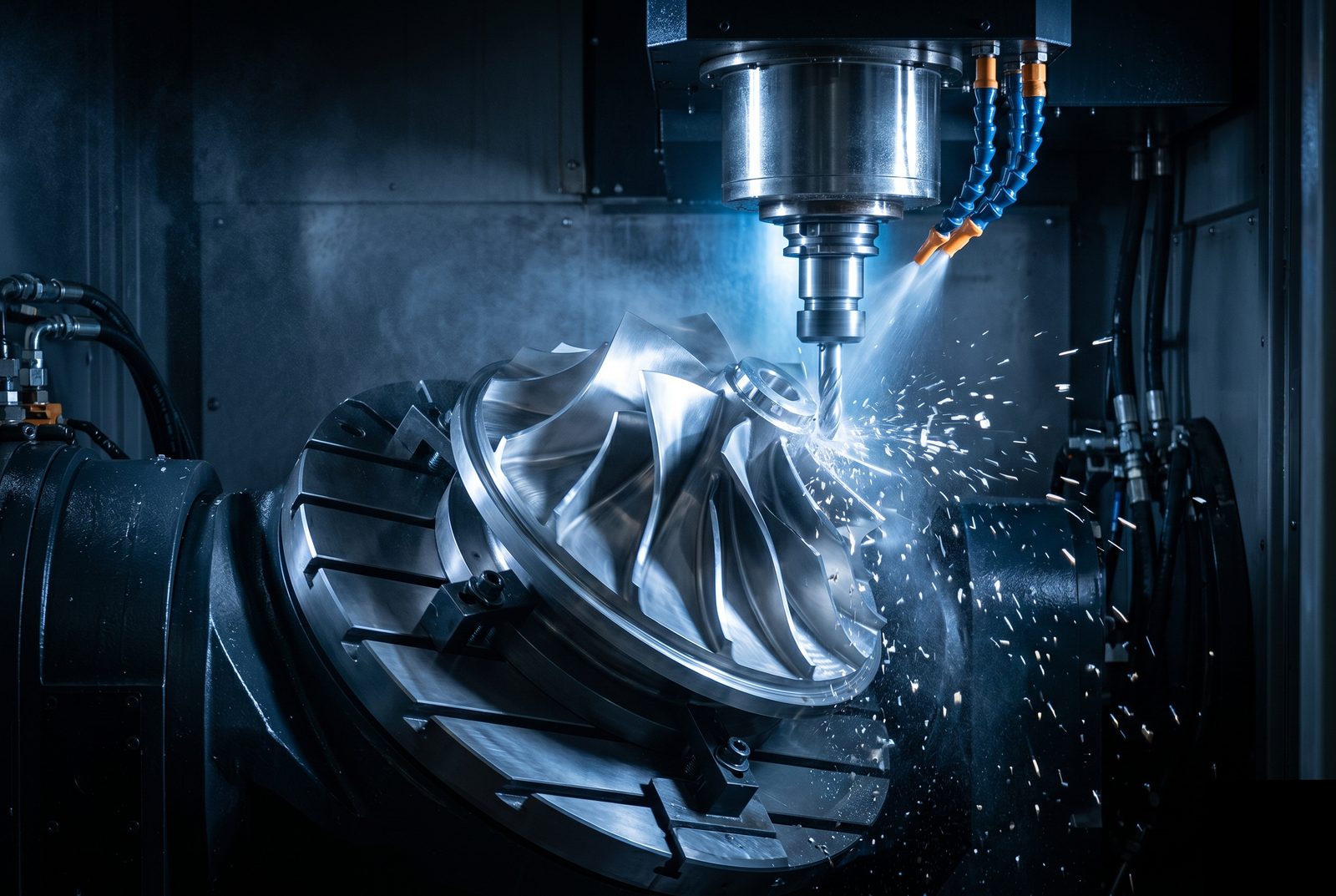
Five-Axis Machining for Geometry a 3-Axis Can't Touch.
Factorem machines complex undercuts, compound angles, and multi-face features in a single setup — eliminating datum shift, reducing lead time, and holding tighter true-position tolerances across all faces.
±0.005mm
Critical feature tolerance
5 axes
Simultaneous or indexed
Single setup
Multi-face features
ISO 9001
Certified
Typical Capability Specs
Common parameters for 5-axis work at Factorem. Many jobs push beyond these numbers — send your file and we'll advise on what's achievable.
Positioning Tolerance
±0.005mm
Critical features. True-position across faces ±0.01mm or better in single setup.
Rotary Range
±110° / 360°
B-axis tilt ±110°, C-axis table full 360°. Covers compound angles and full wrap-around features.
Max Part Envelope
500×400×400mm
Within the rotary table swing. Larger parts reviewed individually through our supplier network.
Angularity
±0.01°
Rotary axis angular repeatability. Validated with on-machine probing on critical programs.
Surface Finish (Ra)
Ra 0.4µm
Achieved on curved surfaces with optimal tool angle. Better than 3-axis scallop patterns.
Lead Time
10–18 days
Typical, depending on complexity. Complex CAM programming for freeform geometry adds time.
Common Materials
5-axis works with the same material range as 3-axis CNC. Titanium and high-strength alloys benefit particularly from 5-axis due to constant tool engagement angle reducing tool wear.
AL 6061-T6 / AL 7075-T6
Most 5-axis aluminium work. 7075 for high-strength flight hardware; 6061 for enclosures, mounts, and optical hardware.
Commonly used for
Compound-curved housings, multi-face brackets, kinematic stages with undercut features
Ti-6Al-4V
5-axis particularly advantageous for titanium — constant tool angle maintains chip load, extends tool life, and improves surface quality versus 3-axis on curved features.
Commonly used for
Cryogenic fixtures, attitude control hardware, structural aero components with compound geometry
SS 316L / 17-4 PH
Vacuum-compatible and high-strength stainless grades. 5-axis enables complex cavity and undercut geometry in single setups for vacuum components.
Commonly used for
Vacuum chambers, complex manifolds, avionics housings with multi-angle connector cutouts
Invar 36
Near-zero CTE for thermally stable optical and quantum lab hardware. Difficult to machine — 5-axis reduces total cutting time and fixturing challenges.
Commonly used for
Optical bench reference frames, interferometer bodies, thermally stable sensor mounts
PEEK / Ultem
High-performance engineering polymers for electrical isolation and thermal management. 5-axis handles complex contoured profiles in one setup.
Commonly used for
Contoured thermal breaks, complex isolator bodies, shaped enclosure covers
Other Materials
Copper, Kovar, hardened tool steels, and other alloys reviewed case-by-case. Send your material and geometry — we'll advise on machinability and strategy.
Have a material or alloy not listed here? Our engineers are happy to advise on 5-axis machinability, tool strategy, and lead time. Most reasonable requests can be accommodated. Talk to an engineer →
Don't see what you need?
Unusual geometry, exotic alloy, or a tolerance callout you've been told can't be done? Send it to our engineers — most non-standard requests can be accommodated.
Industries & Applications
5-axis machining is commonly used where geometry complexity or tolerance relationships across faces demand a single-setup approach. Not limited to these examples.
Photonics & Optics
Kinematic mirror mounts, compound-curve beamsplitter housings, multi-face telescope structures, interferometer bodies
See Photonics page →
Quantum
Ion trap substrates with complex electrode geometry, RF cavity bodies with curved inner surfaces, compound cryogenic mounts
See Quantum page →
Defense & Aerospace
Compound-curved avionics enclosures, multi-face structural brackets, angled connector interfaces, shaped payload housings — EAR99
See Defense page →
Space Tech
Attitude control gimbal bodies, complex RF waveguide flanges, multi-face satellite interface plates, deployment mechanism brackets
See Space Tech page →
Robotics
Complex wrist joint bodies, multi-face actuator housings with angled bore patterns, compound geometry end-effector structures
See Robotics page →
Other Applications
Medical implants, turbomachinery, semiconductor equipment, custom instrumentation — 5-axis applies wherever geometry exceeds 3-axis reach.
Available Surface Finishes
The full finish range available on CNC applies to 5-axis parts. Other finishes available on request — share your spec sheet and we'll confirm.
As-Machined
Ra 0.4–1.6µm on curved surfaces using optimal 5-axis tool angle. Better than equivalent 3-axis finish on freeform.
Anodize Type II / III
MIL-A-8625. All aluminium parts. Hard anodize for wear-critical surfaces on complex geometry.
Chromate Conversion
MIL-DTL-5541. Conductive, corrosion-resistant coating for aluminium parts requiring EMI grounding.
Passivation
ASTM A967 for stainless. Important for vacuum-environment parts — removes free iron contamination.
Electroless Nickel
Uniform coating over complex curved geometry — a key advantage of electroless vs. electrolytic processes.
Bead Blast
Uniform matte finish over all faces including compound curves. Often specified before anodizing for consistent appearance.
Precision Grinding
Ra 0.1–0.2µm on flat datum faces after 5-axis machining. Used for sealing surfaces and optical-grade references.
More on request
Black oxide, gold plating, PVD coatings, specialty aerospace coatings — contact us with your spec.
Design Considerations
Before You Send Your File
Common design considerations for 5-axis parts. Guidance, not hard rules — if your geometry doesn't fit, send it and let us advise.
Flag Undercuts and Angled Features Early
Clearly annotate undercut depths, angled bore directions, and compound angle specs on your drawing. This lets our engineers plan the toolpath strategy before quoting rather than discovering geometry constraints mid-job.
True-Position Tolerances Across Faces
Single-setup 5-axis eliminates datum shift between setups — the key advantage for holding ±0.02mm or tighter positional callouts across multiple faces. If your design has tight cross-face relationships, specify them explicitly on the drawing.
Freeform Surfaces — Provide the CAD Model
For compound-curved or freeform geometry, the STEP file is the drawing — 2D section views don't capture enough information. Include Ra callouts and any curvature tolerances that apply to freeform faces.
Fixturing Access
The rotary table needs a secure clamping face while all machined surfaces remain accessible. Very large flat parts or parts with no good clamping face may need a custom fixture — flag them early.
Complex geometry — compound angles, freeform surfaces, or tight cross-face tolerances?
Talk to our engineersHow a 5-Axis Order Works
From file upload to delivery — what happens at each step for complex geometry.
Upload Your CAD File
Send STEP or IGES with your drawing. Annotate critical tolerances, angularity callouts, and any undercut depths on the drawing so we have full context.
DFM + Axis Strategy Review — Within 24–48 Hours
A Factorem engineer reviews your design, determines indexed vs. simultaneous 5-axis, identifies fixturing approach, and confirms all features are accessible. Complex geometry may take 48 hours for thorough review.
Confirm Quote, Material, & Finish
Fixed-price quote with lead time and documentation requirements confirmed. CAM programming begins immediately on order confirmation.
5-Axis Machining with In-Process Probing
Parts are machined with on-machine probing to verify critical features at each rotary index position. First articles CMM-inspected against your drawing including all angular and true-position callouts.
Documentation & Delivery
Full dimensional inspection report, Certificate of Conformance, and MTR where applicable. Tracked shipment with complete handover documentation.
5-Axis Machining FAQ
5-axis is the right choice when your part has undercuts, compound angles, multi-face features that would require multiple 3-axis setups, or freeform surfaces like turbine blades or compound curved housings. It's also used when tight angularity or positional tolerances are needed across features on different faces — single-setup machining eliminates accumulation of setup error. Not sure? Send the file and we'll specify the right approach during DFM review.
Simultaneous 5-axis moves all five axes at once — allowing the cutter to follow complex freeform surfaces while maintaining constant tool engagement. It's needed for turbine blades, impellers, compound-curved optical housings, and similar geometry. Indexed 5-axis (3+2) positions the part at multiple angles but cuts with 3-axis motion — suitable for most undercut and multi-face parts at lower cost. Our DFM review determines which approach suits your part.
We hold ±0.005mm on critical features. The advantage of 5-axis for tolerance is that single-setup machining eliminates datum shift between setups — so related features on different faces hold their positional relationship more accurately than multi-setup 3-axis. Angularity and true position across faces are typically ±0.01mm or better.
Undercut features, angled holes and pockets, compound-curved surfaces, parts requiring machining on 4+ faces, and tight true-position tolerances across multiple faces. 5-axis also improves surface finish on curved surfaces by maintaining optimal tool angle throughout the cut — reducing scallop height and improving Ra versus 3-axis ball-end milling.
The same material range as 3-axis CNC: AL 6061/7075, Ti-6Al-4V, SS 316L/17-4 PH, Invar 36, PEEK, and others on request. Titanium and hardened steels particularly benefit from 5-axis because constant tool engagement angle reduces tool wear and improves surface quality on these difficult-to-machine materials.
Yes. Indexed 5-axis (3+2) positions the part at a fixed angle then cuts with 3-axis motion — it handles most undercut and multi-face work at lower programming time and cost. Simultaneous 5-axis is used for freeform surfaces and complex geometry where the tool must maintain a constantly changing angle relative to the surface. Our DFM review determines which approach suits your part and budget.
Have a Part That Needs 5-Axis?
Upload your file and we'll review the geometry, confirm axis requirements, and come back with a fixed-price quote. Or talk to an engineer first.
DFM review within 24–48 hours · Fixed-price quote · Full documentation on every order